Instrument Cluster: Difference between revisions
From OpenGK
No edit summary |
|||
| (3 intermediate revisions by the same user not shown) | |||
| Line 8: | Line 8: | ||
==Pinout and signals== | ==Pinout and signals== | ||
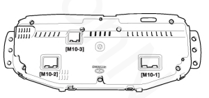
[[File:Instrument cluster.png|none|thumb]] | |||
{| class="wikitable" | |||
|+M10-1 | |||
!# | |||
!Name | |||
!Notes | |||
|- | |||
|1 | |||
|Ground | |||
| | |||
|- | |||
|2 | |||
|Injection signal (for FCO calculation) | |||
| | |||
|- | |||
|3 | |||
|Power (ign on or start) | |||
| | |||
|- | |||
|4 | |||
|Cruise control "CRUISE" indicator | |||
| | |||
|- | |||
|5 | |||
|Trunk open indicator | |||
| | |||
|- | |||
|6 | |||
|Tachometer | |||
| | |||
|- | |||
|7 | |||
|Water temperature gauge | |||
| | |||
|- | |||
|8 | |||
|Ground | |||
| | |||
|- | |||
|9 | |||
|High beam indicator | |||
| | |||
|- | |||
|10 | |||
|Right turn indicator | |||
| | |||
|- | |||
|11 | |||
|Cruise control "SET" indicator | |||
| | |||
|- | |||
|12 | |||
|Charging indicator | |||
| | |||
|- | |||
|13 | |||
|Oil pressure indicator | |||
| | |||
|- | |||
|14 | |||
|Check Engine Light indicator | |||
| | |||
|- | |||
|15 | |||
|ESP off indicator | |||
| | |||
|- | |||
|16 | |||
| | |||
| | |||
|- | |||
|17 | |||
|Vehicle speed input | |||
| | |||
|- | |||
|18 | |||
|Fuel sender | |||
| | |||
|- | |||
|19 | |||
|Fuel gauge ground | |||
| | |||
|- | |||
|20 | |||
|Power | |||
| | |||
|} | |||
{| class="wikitable" | |||
|+M10-2 | |||
!# | |||
!Name | |||
!Notes | |||
|- | |||
|1 | |||
|Left turn indicator | |||
| | |||
|- | |||
|2 | |||
|Low fuel indicator | |||
| | |||
|- | |||
|3 | |||
|Power (ign on or start) | |||
| | |||
|- | |||
|4 | |||
|Airbag indicator | |||
| | |||
|- | |||
|5 | |||
|Ground | |||
| | |||
|- | |||
|6 | |||
|Open door indicator | |||
| | |||
|- | |||
|7 | |||
|Power from fuse #18 (hot at all times) | |||
| | |||
|- | |||
|8 | |||
|Brake indicator | |||
| | |||
|- | |||
|9 | |||
|Seatbelt indicator | |||
| | |||
|- | |||
|10 | |||
|TPMS check (symbol) | |||
| | |||
|- | |||
|11 | |||
|ABS indicator | |||
| | |||
|- | |||
|12 | |||
|ESP indicator | |||
| | |||
|- | |||
|13 | |||
|TPMS fail (indicator) | |||
| | |||
|- | |||
|14 | |||
|Immobilizer indicator | |||
| | |||
|- | |||
|15 | |||
|Illumination + | |||
| | |||
|- | |||
|16 | |||
|Illumination - | |||
| | |||
|} | |||
{| class="wikitable" | |||
|+M10-3 (only present in AT clusters) | |||
!# | |||
!Name | |||
!Notes | |||
|- | |||
|1 | |||
|Parking gear indicator | |||
| | |||
|- | |||
|2 | |||
|Reverse gear indicator | |||
| | |||
|- | |||
|3 | |||
|Neutral drive indicator | |||
| | |||
|- | |||
|4 | |||
|Drive gear indicator | |||
| | |||
|- | |||
|5 | |||
|PWM active gear signal | |||
|1: 10-19% 2: 20-34% 3: 35-49% 4: 50-100% | |||
|} | |||
==EEPROM data structure== | ==EEPROM data structure== | ||
==PCB layout== | ==PCB layout== | ||
Latest revision as of 17:22, 28 January 2024
| This article is a stub. You can help by contributing your knowledge of the Tiburon platform |
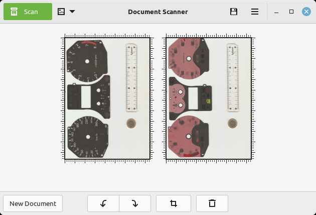
(60.3MB) High resolution (2400dpi) scan of EU/metric GK cluster faces, front and back
Variants
Pinout and signals

| # | Name | Notes |
|---|---|---|
| 1 | Ground | |
| 2 | Injection signal (for FCO calculation) | |
| 3 | Power (ign on or start) | |
| 4 | Cruise control "CRUISE" indicator | |
| 5 | Trunk open indicator | |
| 6 | Tachometer | |
| 7 | Water temperature gauge | |
| 8 | Ground | |
| 9 | High beam indicator | |
| 10 | Right turn indicator | |
| 11 | Cruise control "SET" indicator | |
| 12 | Charging indicator | |
| 13 | Oil pressure indicator | |
| 14 | Check Engine Light indicator | |
| 15 | ESP off indicator | |
| 16 | ||
| 17 | Vehicle speed input | |
| 18 | Fuel sender | |
| 19 | Fuel gauge ground | |
| 20 | Power |
| # | Name | Notes |
|---|---|---|
| 1 | Left turn indicator | |
| 2 | Low fuel indicator | |
| 3 | Power (ign on or start) | |
| 4 | Airbag indicator | |
| 5 | Ground | |
| 6 | Open door indicator | |
| 7 | Power from fuse #18 (hot at all times) | |
| 8 | Brake indicator | |
| 9 | Seatbelt indicator | |
| 10 | TPMS check (symbol) | |
| 11 | ABS indicator | |
| 12 | ESP indicator | |
| 13 | TPMS fail (indicator) | |
| 14 | Immobilizer indicator | |
| 15 | Illumination + | |
| 16 | Illumination - |
| # | Name | Notes |
|---|---|---|
| 1 | Parking gear indicator | |
| 2 | Reverse gear indicator | |
| 3 | Neutral drive indicator | |
| 4 | Drive gear indicator | |
| 5 | PWM active gear signal | 1: 10-19% 2: 20-34% 3: 35-49% 4: 50-100% |


