Creating a test bench setup
This article won't cover the most basic ECU<>K-Line adapter connection since all information required for that can be found in the ECU pinout pages.
Instead, we will focus on creating a more complete environment that'll reassemble the actual car - allowing you to swap parts, test inter-connected systems such as the immobiliser, and most importantly - research. The purpose of this article is mostly to organize connector part numbers and pinouts in one place so the process is more straightforward for the next person

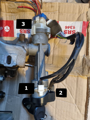
Ignition switch - key sensor, immobiliser antenna, illumination
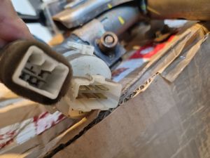
Ignition switch connector
Female (harness) side connector: KUM PH772-06015
Female (harness) side terminals: Faston 6.3mm
| Ignition switch pinout. Female side, looking from the front
<tab> | ||
|---|---|---|
| #3. Ignition output | #2. +12v input | #1. Starter output |
| #6. Ignition output | #5. +12v input | #4. Accessory output |
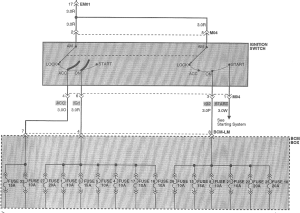
As seen in the diagram below, #3 and #6 power different BCM fuses but they're essentially the same and swapping them won't do any harm


Key sensor, immobiliser antenna, key illumination
Female (harness) side connector: KET MG651044 / Yazaki 7283-1060
Female (harness) side terminals: ???
| Key sensor pinout. Female side, looking from the front
<tab> | |||
|---|---|---|---|
| #2. Immobiliser antenna
(BCM-HM 1) |
#1. Immobiliser antena
(BCM-HM 11) | ||
| #6. Ground | #5. Key sensor
(BCM-HM 4) |
#4. Key sensor
(BCM-JM 3) |
#3. +12v illumination input
(BCM-KM 10) |

