Data link connector (OBD2): Difference between revisions
From OpenGK
(obd2 pinout) |
(add port picture. TODO: replace with own photo, not a youtube thumbnail) |
||
| Line 1: | Line 1: | ||
==Location== | ==Location== | ||
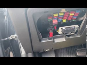
[https://en.wikipedia.org/wiki/On-board_diagnostics#OBD-II OBD2 port] on the Tiburon is hidden behind the [[Body Control Module|fusebox cover]] located right under the steering wheel. | [https://en.wikipedia.org/wiki/On-board_diagnostics#OBD-II OBD2 port] on the Tiburon is hidden behind the [[Body Control Module|fusebox cover]] located right under the steering wheel. | ||
[[File:Obd2 location.jpg|center|thumb|OBD2 port (bottom right corner, black connector on silver plate)]] | |||
==Pinout== | ==Pinout== | ||
| Line 19: | Line 20: | ||
|- valign="top" | |- valign="top" | ||
!3 | !3 | ||
|'''Speed sensor'''<br> | |'''Vehicle Speed sensor'''<br>Going directly into pin 3 of vehicle's speed sensor | ||
!11 | !11 | ||
| | | | ||
| Line 28: | Line 28: | ||
!12 | !12 | ||
|'''Airbag''' | |'''Airbag''' | ||
Goes into pin 16 of [[Body Control Module|BCM]]'s BCM-IM connector | |||
|- valign="top" | |- valign="top" | ||
! style="background-color: gray" |5 | ! style="background-color: gray" |5 | ||
| Line 52: | Line 53: | ||
|- valign="top" | |- valign="top" | ||
!8 | !8 | ||
|'''ABS/ESP'''<br> | |'''ABS/ESP'''<br>Goes directly into ABS/ESP module and | ||
the "ESC AIR BLEEDING CONNECTOR" | |||
(if equipped with traction control) | |||
! style="background-color: red" |16 | ! style="background-color: red" |16 | ||
|'''Battery voltage ("Memory Power")'''<br> | |'''Battery voltage ("Memory Power")'''<br> | ||
+12 Volt | +12 Volt | ||
|} | |} | ||
For more CAN information, see [[SIMK43 CAN Bus]]<references /> | |||
<references /> | |||
Revision as of 06:30, 22 August 2023
Location
OBD2 port on the Tiburon is hidden behind the fusebox cover located right under the steering wheel.

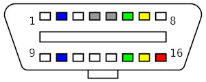
Pinout

| 1 | 9 | ||
|---|---|---|---|
| 2 | Bus positive Line | 10 | Bus negative Line |
| 3 | Vehicle Speed sensor Going directly into pin 3 of vehicle's speed sensor |
11 | |
| 4 | Chassis ground | 12 | Airbag
Goes into pin 16 of BCM's BCM-IM connector |
| 5 | Signal ground ("Sensor ground") | 13 | |
| 6 | CAN high (ISO 15765-4 and SAE J2284) |
14 | CAN low (ISO 15765-4 and SAE J2284) |
| 7 | K-line (ISO 9141-2 and ISO 14230-4) |
15 | Battery voltage This should be L-line (ISO 9141-2 & 14230-4) but according to Hyundai diagrams it's called DCT and provides 12v+ from BCM's "V-PUP" |
| 8 | ABS/ESP Goes directly into ABS/ESP module and the "ESC AIR BLEEDING CONNECTOR" (if equipped with traction control) |
16 | Battery voltage ("Memory Power") +12 Volt |
For more CAN information, see SIMK43 CAN Bus
