(Fixed the part about grounding the BOOT pin. Puling pins hard to ground without a pulldown resistor is dangerous and may cause the I/O circuitry inside the MCU to burn up since it's essentially shorted.)
# Connect [[K-Line]] per [[Siemens 5WY 2 Connector Pinout|ECU pinout]]
# Connect [[K-Line]] per [[Siemens 5WY 2 Connector Pinout|ECU pinout.]]
# Ground the BOOT pin<ref name=":0">You can use a 10K resistor, then there's no need to disconnect it for the duration of BSL </ref>
# Pull down the BOOT pin to Ground through a 10kΩ resistor.
# Connect power to the ECU
# Connect power to the ECU.
# ECU is now ready for BSL input - you can press any button in the BSL tab in GKFlasher
# ECU is now ready for BSL input - you can press any button in the BSL tab in GKFlasher.
# Once communication has been estabilished, unground the BOOT pin. It is part of the addressing pins and it will cause memory to be corrupted if left grounded
=== Immo ECUs ===
=== Immo ECUs ===
# Connect K-Line per [[Siemens 5WY 2 Connector Pinout|ECU pinout]]
# Connect K-Line per [[Siemens 5WY 2 Connector Pinout|ECU pinout]]
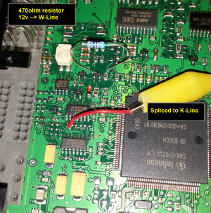
# [[File:Bsl pins dmg210.png|thumb]]Attach a 470ohm resistor on the [[W-Line|W-Line<small>(? citation needed)</small>]] and splice [[K-Line]] into [[K-Line]] on the ECU header - if you're using a Y-split OBD2 cable, that'd be [[Data link connector (OBD2)|pin 9]]
# [[File:Bsl pins dmg210.png|thumb]]Attach a 470Ω resistor on the [[W-Line|W-Line<small>(? citation needed)</small>]] and splice [[K-Line]] into [[K-Line]] on the ECU header - if you're using a Y-split OBD2 cable, that'd be [[Data link connector (OBD2)|pin 9]].
# Ground the BOOT pin<ref name=":0" />
# Pull down the BOOT pin to Ground through a 10kΩ resistor.
# Connect power to the ECU
# Connect power to the ECU.
# ECU is now ready for BSL input - you can press any button in the BSL tab in GKFlasher
# ECU is now ready for BSL input - you can press any button in the BSL tab in GKFlasher.
# Once communication has been estabilished, unground the BOOT pin. It is part of the addressing pins and it will cause memory to be corrupted if left grounded
Revision as of 08:33, 5 July 2026
This article is a stub. You can help by contributing your knowledge of the Tiburon platform
Bootstrap Loader (BSL) on the C166 MCUs allows to execute code in memory, bypassing code stored on the EEPROM.
This is often used to flash regions of memory inaccessible through OBD2, such as the bootloader. Most notable case would be removing the immobiliser, or performing a ca663056->ca663057 upgrade, which requires changing the bootloader.
To enter BSL mode, you must ground the BOOT pin and then feed power to the ECU, which will make the CPU wait for input over serial port instead of executing code stored on the flash memory. Then, typically a small loader is uploaded which later faciliates upload and execution of the proper BSL program, which will offer ways to manipulate memory.