Data link connector (OBD2): Difference between revisions
From OpenGK
No edit summary |
(→Pinout) |
||
| (6 intermediate revisions by the same user not shown) | |||
| Line 4: | Line 4: | ||
==Pinout== | ==Pinout== | ||
{{Warning|'''THIS PINOUT IS OF THE HARNESS SIDE FEMALE CONNECTOR, AS IT'S SUPPOSED TO BE!''' OEM wiring diagrams reference male OBD2 '''plug''' instead. Assigned pin numbers will be mirrored between OEM's and diagram below. }} | |||
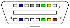
[[File:OBDII female type A.jpg|thumb|Female (vehicle's side) OBD-II connector pinout - front view]] | [[File:OBDII female type A.jpg|thumb|Female (vehicle's side) OBD-II connector pinout - front view]] | ||
| Line 15: | Line 17: | ||
|- valign="top" | |- valign="top" | ||
! style="background-color: blue" |2 | ! style="background-color: blue" |2 | ||
| | |Not connected | ||
! style="background-color: blue" |10 | ! style="background-color: blue" |10 | ||
| | |Not connected | ||
|- valign="top" | |- valign="top" | ||
!3 | !3 | ||
| Line 43: | Line 45: | ||
|- valign="top" | |- valign="top" | ||
! style="background-color: yellow" |7 | ! style="background-color: yellow" |7 | ||
|'''K-line'''<br> | |[[K-Line|'''K-line'''<br>]] | ||
(ISO 9141-2 &/ KWP2000) | (ISO 9141-2 &/ KWP2000) | ||
! style="background-color: yellow" |15 | ! style="background-color: yellow" |15 | ||
|''' | |'''[[L-line|L-Line]]'''<br>Needs to be grounded to access [[Body Control Module|BCM]] diagnostics. | ||
|- valign="top" | |- valign="top" | ||
!8 | !8 | ||
| Line 61: | Line 59: | ||
+12 Volt | +12 Volt | ||
|} | |} | ||
For more CAN information, see [[SIMK43 CAN Bus]]<references /> | |||
==== For more CAN information, see [[SIMK43 CAN Bus]] ==== | |||
==== For more K-line information, see [[K-Line]] ==== | |||
<references /> | |||
Latest revision as of 11:37, 14 January 2024
Location
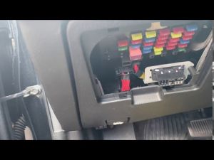
OBD2 port on the Tiburon is hidden behind the fusebox cover located right under the steering wheel.

Pinout

| 1 | 9 | ||
|---|---|---|---|
| 2 | Not connected | 10 | Not connected |
| 3 | Vehicle Speed sensor Going directly into pin 3 of vehicle's speed sensor |
11 | |
| 4 | Chassis ground | 12 | Airbag
Goes into pin 16 of BCM's BCM-IM connector |
| 5 | Signal ground ("Sensor ground") | 13 | |
| 6 | CAN high (ISO 15765-4 and SAE J2284) |
14 | CAN low (ISO 15765-4 and SAE J2284) |
| 7 | K-line (ISO 9141-2 &/ KWP2000) |
15 | L-Line Needs to be grounded to access BCM diagnostics. |
| 8 | ABS/ESP Goes directly into ABS/ESP module and the "ESC AIR BLEEDING CONNECTOR" (if equipped with traction control) |
16 | Battery voltage ("Memory Power") +12 Volt |

