(8 intermediate revisions by the same user not shown) Line 1:
Line 1: {{Stub}}
{{Stub}}
https://fccid.io/LXP-VIM233
BCM FCC report: https://fccid.io/LXP-VIM233
GK Keyfob FCC report: https://fcc.report/FCC-ID/LXP-RKE225
FL2 Keyfob FCC report: https://fcc.report/FCC-ID/LXP-RK225
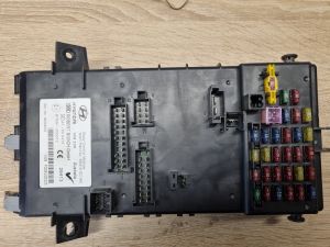
[[File:BCM module front 95410-2C160.jpg|thumb|BCM module front 95410-2C160 (EU, 2.0, VIN: KMHHN61DP2U038775)]]
[[File:BCM module front 95410-2C160.jpg|thumb|BCM module front 95410-2C160 (EU, 2.0, VIN: KMHHN61DP2U038775)]]
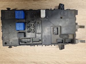
[[File:BCM module back 95410-2C160.jpg|thumb|BCM module back 95410-2C160 (EU, 2.0, VIN: KMHHN61DP2U038775)]]
[[File:BCM module back 95410-2C160.jpg|thumb|BCM module back 95410-2C160 (EU, 2.0, VIN: KMHHN61DP2U038775)]]
==Variants==
==PCB Layouts ==
[[BCM 95410-2C100]]
[[BCM 95410-2C160]] (the one this page is based on)
[[BCM 95480-2C310]]
==Pinout==
==Pinout==
Line 850:
Line 859: ==FLASH EEPROM structure==
==FLASH EEPROM structure==
64KiB of memory is located inside of the Motorola MC68HC908A microcontroller
64KiB of memory is located inside of the Motorola MC68HC908A microcontroller [[:File:311-21300-0-MC908AZ32ACFU.pdf]]
==PCB layout==
== PCB layout of the 95410-2C160 ==
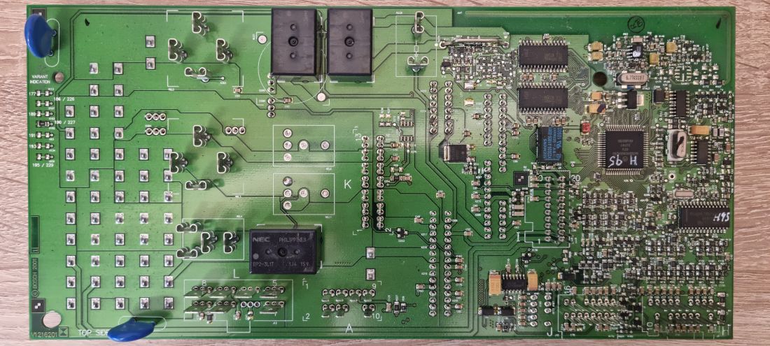
[[File:BCM module PCB front 95410-2C160 (EU, 2.0).jpg|none|thumb|1100x1100px|'''BCM module PCB front 95410-2C160 (EU, 2.0)''']]
For the demonstration purposes of this page, one of the earliest and simplest variant was selected. [[File:BCM module PCB front 95410-2C160 (EU, 2.0).jpg|none|thumb|1100x1100px|BCM module PCB front 95410-2C160 (EU, 2.0, VIN: KMHHN61DP2U038775 )]]
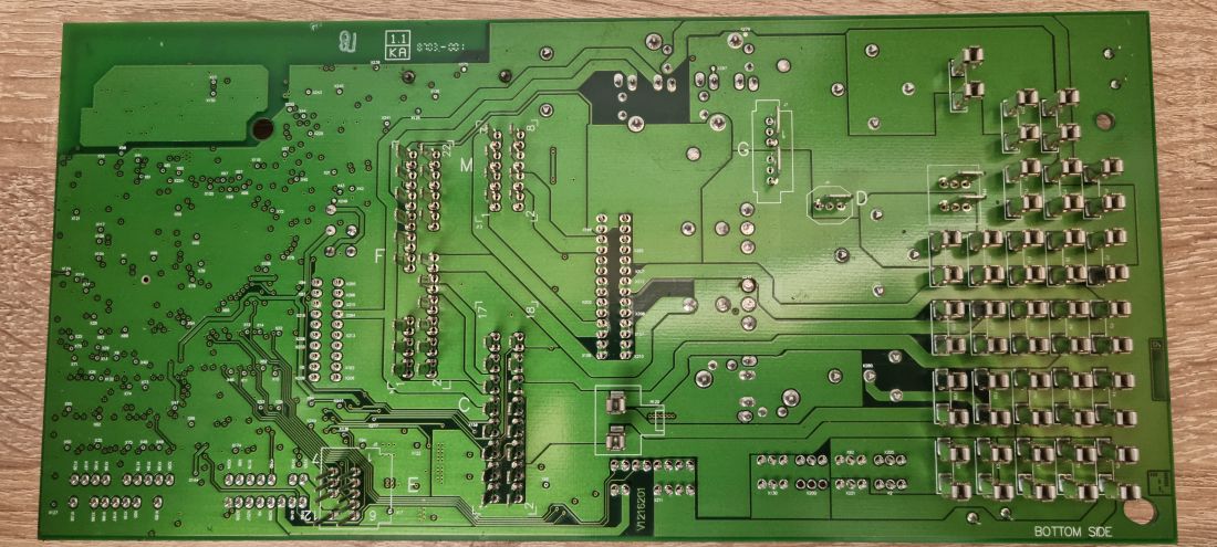
[[File:BCM module PCB back 95410-2C160 (EU, 2.0).jpg|none|thumb|1100x1100px|BCM module PCB back 95410-2C160 (EU, 2.0)]]
[[File:BCM module PCB back 95410-2C160 (EU, 2.0).jpg|none|thumb|1100x1100px|BCM module PCB back 95410-2C160 (EU, 2.0, VIN: KMHHN61DP2U038775 )]]
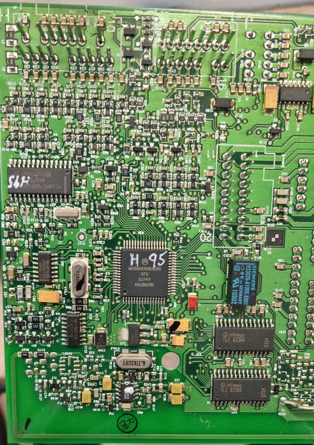
[[File:BCM module PCB microcontrollers closeup 95410-2C160 (EU, 2.0).jpg|none|thumb|1559x1559px|BCM module PCB microcontrollers closeup 95410-2C160 (EU, 2.0)]]
[[File:BCM module PCB microcontrollers closeup 95410-2C160 (EU, 2.0).jpg|none|thumb|1559x1559px|BCM module PCB microcontrollers closeup 95410-2C160 (EU, 2.0, VIN: KMHHN61DP2U038775 )]]
Our BCM's use an 8bit Motorola CPU: MC68HC908A. [[:File:311-21300-0-MC908AZ32ACFU.pdf]]
Our BCM's use an 8bit Motorola CPU: MC68HC908AZ60 running at 8Mhz . [[:File:311-21300-0-MC908AZ32ACFU.pdf]]
Latest revision as of 01:10, 17 April 2025
This article is a stub. You can help by contributing your knowledge of the Tiburon platform
BCM FCC report: https://fccid.io/LXP-VIM233
GK Keyfob FCC report: https://fcc.report/FCC-ID/LXP-RKE225
FL2 Keyfob FCC report: https://fcc.report/FCC-ID/LXP-RK225
BCM module front 95410-2C160 (EU, 2.0, VIN: KMHHN61DP2U038775) BCM module back 95410-2C160 (EU, 2.0, VIN: KMHHN61DP2U038775) PCB Layouts BCM 95410-2C100
BCM 95410-2C160 (the one this page is based on)
BCM 95480-2C310
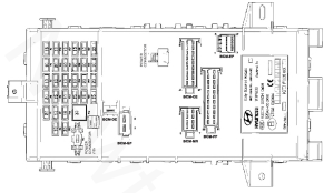
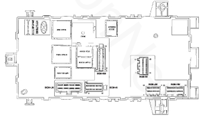
Pinout BCM front connectors BCM rear connectors
BCM-AA
Expand
#
Type
Name
Notes
1
-
2
-
3
-
4
ESPS (ig1)
5
RH seat belt buckle
6
LH seat belt buckle
7
Input
Crash signal
8
9
Input
Airbag diagnosis (from ESPS)
10
Output
Airbag warning light
BCM-CE
Expand
#
Type
Name
Notes
1
Output
Head lamp low relay (S2)
2
DRL unit NO 12
3
Output
Front wiper relay control
4
Output
Front fog lamp relay (S1)
5
Turn signal lamp (FR)
6
Tail auto cut to DRL
7
DRL unit (11)
8
Output
Front wiper relay (IG2)
9
Output
Turn signal lamp (FL)
10
Output
Position lamp (RH)
11
Output
Position lamp (LH)
12
Output
ABS module (IG1)
13
Output
Alternator charge line / dash indicator
14
Output
Fuse & relay box (IG2) (Ignition fuse)
15
Output
Wiper park output
16
Output
Washer motor
17
-
18
-
BCM-DE
Expand
#
Type
Name
Notes
1
Input
Battery
BCM-EF - TE 175965-2
Expand
#
Type
Name
Notes
1
Input
Assist door key switch
2
Input
Tail gate lock switch
3
Input
Assist door lock switch
4
Input
Assist door switch
5
Input
Folding switch
6
Input
Tail gate open switch
7
Input
Driver door key unlock switch
8
Input
Driver door lock switch
9
Input
Driver door switch
10
Input
Seat belt switch
11
-
12
-
BCM-FF
Expand
#
Type
Name
Notes
1
Output
Rear fog lamp relay
2
Output
Back up lamp
3
-
4
Output
Outside mirror
5
Output
Tail lamp (RH)
6
Output
Door lock relay
7
-
8
Output
Door unlock relay
9
-
10
Output
Tail lamp (LH) fuse
11
Input
Door switch
12
Output
Mirror unfolding/door unlock relay
13
Turn signal (RL)
14
-
15
Output
Luggage lamp
16
-
17
Turn signal (RR)
18
Output
Amplifier
19
Output
Outside mirror heater
20
Mirror folding
21
Output
Rear wiper motor (IG2)
22
Input
Tail gate open switch
BCM-GF
Expand
#
Type
Name
Notes
1
Output
Rear window defogger
2
Output
Power window relay
BCM-HM
Expand
#
Type
Name
Notes
1
IO
Immobilizer antenna 1
2
Output
2 stage unlock ground
3
Input
Turn signal switch (RH)
4
Input
Door warning switch
5
Input
Tail lamp switch
6
Input
Rear fog lamp switch
7
Input
Code saver
8
-
9
Input
Hood switch
10
-
11
IO
Immobilizer antenna 2
12
Output
Export ground
13
Input
Turn signal lamp switch
14
Input
Auto light switch input
15
-
16
Input
Head lamp switch
17
Input
Front fog lamp switch
18
Input
Hazard lamp switch
19
Input
Rear defogger switch
20
Output
Rear fog lamp indicator
BCM-IM
Expand
#
Type
Name
Notes
1
Input
Air conditioner switch
2
Output
Cluster battery charge
3
-
4
ESP switch (IG1)
5
Output
Cluster (IG1)
6
Output
Cluster (IG2)
7
Output
Cluster (turn signal LH out)
8
ECU (IG1)
9
Output
Cluster (turn signal RH out)
10
RR HTD switch
11
Output
Cluster (airbag indicator)
12
Diagnostic tool (B+)
13
Output
Digital clock (ACC)
14
Output
Immobilizer indicator
15
External tail lamp (RH)
16
Diagnostic tool (Airbag)
17
Air conditioner (IG2)
18
Auto light ground
19
Diagnosis & code saving
20
Immobilizer
BCM-JM
Expand
#
Type
Name
Notes
1
Multifunction switch - intermittent wiper ground
2
Siren control
3
Output
Key hole illumination
4
Input
Speed sensor
5
Output
Interior illumination
6
Output
Cluster (Airbag warning indicator)
7
DCT
8
Output
Door open indicator
9
Multifunction INT
10
Multifunction INT (T)
11
Auto light signal
12
Output
Seat belt indicator
13
Output
Over speed ground
14
-
15
Auto light supply
16
Output
Tail gate open indicator
BCM-KM
Expand
#
Type
Name
Notes
1
Output
Cigar lighter
2
Wiper low
3
Wiper high
4
Back up switch (reverse gear)
5
ACC
6
Input
Washer switch
7
Input
Back up lamp switch
8
Start inhibit relay
9
Input
Seat heater switch (IG2)
10
Joint main 3 (B+)
11
Input
Stop switch (B+)
12
Ignition coil
13
-
14
Wiper parking
BCM-LM
Expand
#
Type
Name
Notes
1
Ground 1
2
-
3
Output
Blower motor
4
Ignition switch (IG1)
5
Ground 2
6
Wiper switch power
7
Ignition switch (ACC)
8
Ignition switch (IG2)
BCM-MR
Expand
#
Type
Name
Notes
1
Sunroof (IG2)
2
Roof lamp (B+)
3
Roof lamp decay control
4
ECU
5
-
6
Sunroof & room lamp ground
7
ECM mirror
8
Sunroof (B+)
FLASH EEPROM structure 64KiB of memory is located inside of the Motorola MC68HC908A microcontroller File:311-21300-0-MC908AZ32ACFU.pdf
PCB layout of the 95410-2C160
For the demonstration purposes of this page, one of the earliest and simplest variant was selected.
BCM module PCB front 95410-2C160 (EU, 2.0, VIN: KMHHN61DP2U038775) BCM module PCB back 95410-2C160 (EU, 2.0, VIN: KMHHN61DP2U038775) BCM module PCB microcontrollers closeup 95410-2C160 (EU, 2.0, VIN: KMHHN61DP2U038775) File:311-21300-0-MC908AZ32ACFU.pdf
